Page 1 of 1
Oil Flow Diagram & Pressure Switch
Posted: Sat Feb 28, 2009 8:45 pm
by macx
I give up!
Some time ago I found an oil flow diagram and what I believe to be the location of the switch.
Now I can't find either.
Anybody point me in the right direction?
I believe I've read it's at about 2:00 from the oil level window?
Not real light in the garage, but couldn't ID it when I looked.
Thanks!!
Re: Oil Flow Diagram & Pressure Switch
Posted: Sun Mar 01, 2009 8:52 am
by boxermania
Under the left cylinder.....right above and to the right of the oil window
http://picasaweb.google.com/lh/photo/YU ... directlink
Hope it helps.........
Re: Oil Flow Diagram & Pressure Switch
Posted: Sun Mar 01, 2009 4:05 pm
by TracyPrier
Yep...dat's it

I'm going to install a brass T piece so I can add an oil temp sender
cheers
Tracy
It's Already There
Posted: Sun Mar 01, 2009 11:47 pm
by maduko
Ironic that all our bikes have one.
If only we could tap on to the signal for the Motronic and read it!
Re: Oil Flow Diagram & Pressure Switch
Posted: Mon Mar 02, 2009 12:45 am
by CycleRob
"
If only we could tap on to the signal for the Motronic and read it!"
Your dash's red oil pressure lite already reads it. The pressure switch only contains a make/break pressure switch at about +4psi.
The temp switch adjacent to the oil cooler thermostat is the one worth "tapping into" but I don't think the Motronic would tolerate the "sharing" of temperature information.

Re: Oil Flow Diagram & Pressure Switch
Posted: Mon Mar 02, 2009 5:42 am
by boxermania
The temp switch adjacent to the oil cooler thermostat is the one worth "tapping into" but I don't think the Motronic would tolerate the "sharing" of temperature information
I agree as these switches are nothing more than a variable resistor, where the resistance changes as a function of temperature and a pre-selected applied voltage changes as resistance changes. The ECU is programed to see the voltage changes as temperature changes.
One could set up a simple experiment......with a digital VOM (high input inpedance so as not to load the circuit) tap onto the signal and record the range of voltage during bike operation. Then remove the sensor and generate a curve of resistance vs temperature in your spouses kitchen, using her pots under a verbal barrage of getting oil and dirt on her kitchen.....under the auspices that she will throw out everything used for the experiment, which you will replace in kind.
Then obtain a rangeable 3 1/2 digit readout that accepts DC voltage as an input and is powered externally......
Ahhhh way too much fun, I think I'll tap off the main gallery..............

Re: Oil Flow Diagram & Pressure Switch
Posted: Mon Mar 02, 2009 3:55 pm
by challey
Tracy said:I'm going to install a brass T piece so I can add an oil temp sender
I think more than a couple of us would really appreciate getting some details and seeing some pictures of your install if at all possible. Having an oil temp gauge would really be useful but I'm a bit chicken to try tapping the blind hole that Cycle Rob used in his set up.
Charlie
Re: Oil Flow Diagram & Pressure Switch
Posted: Tue Mar 03, 2009 1:35 pm
by macx
I've been wishing for both an oil pressure and temp gauge - have them on a couple of my
vehicles and it's surprising how much info it gives you as you're driving under diff conditions.
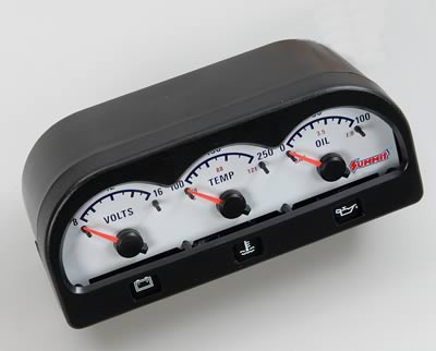
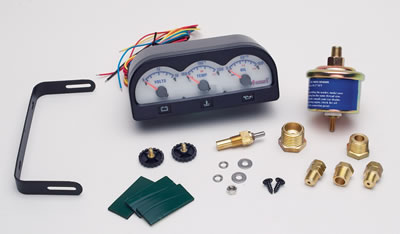
I found a neat little mini gauge panel on Summit for about $65, looks like it's enclosed and has
a mount with it that mite at least help mount it on the bars. I think it's like 5" long. Gauges are
1-1/2".
http://store.summitracing.com/egnsearch ... ults=false
I was hoping I could put a T in at the oil pressure port and put the sender there for the gauges.
For oil temp, I've looked under the bike at the drain plug and have just about convinced myself
to give that a try. I don't do ANY gravel riding with my bike and when you think of it it's not a
whole not more vulnerable than lots of things on the underside of a car. If something would
happen to bounce up and screw up the sender, I doubt if it would do any other damage so the
oil would run out anyway. It would most likely give the most accurate temp reading too.
Found a Stewart Warner adapter - th the threads in the pan are M16x1.5 and SW makes a brass
adapter for a 1/8" electric temp sender. It would hardly stick down below the fins on the bottom
of the pan, and it would take a hit from something fairlymajor to hurt it, so think it would be
worth a try.
http://www.sw-performance.com/index.php ... s&p=114851
Probly be a couple months till I try that, but I'll post if/when I do and with some pics.
Re: Oil Flow Diagram & Pressure Switch
Posted: Wed Mar 04, 2009 12:28 am
by CycleRob
Very nice. Where to put it is the biggest problem.
Re: Oil Flow Diagram & Pressure Switch
Posted: Wed Mar 04, 2009 8:27 am
by Sunbeemer
Re: Oil Flow Diagram & Pressure Switch
Posted: Wed Mar 04, 2009 9:05 pm
by macx
If vibration failure is a concern, one might be able to use a stainless short nipple and T.
They'd be LOTS stronger.
As far as mounting location, I haven't physically measured, but I was thinking of mounting
on the bars between the risers, either between the risers or using maybe even the mount
bracket that comes with that kit to get the bottom of the gauge pod just above the risers.
Or making maybe a sturdier mount bracket. Or how about a bracket that would bolt under
the riser bolt heads? Like a flat plate that comes out to the rear of the bars and then use
that kit bracket, or a sturdier one like it, to bolt to that plate. There's always a way!

The sender with those gauges is sort of big, more like a car sender, so using SS fitting might
be a good idea. You'd maybe have to put the existing sender in the end of the T straight oujt
from where it is now, and point the leg of the T downward where there might be more room for
the larger gauge sender.


